ESP32-BlueJammer - by @emensta
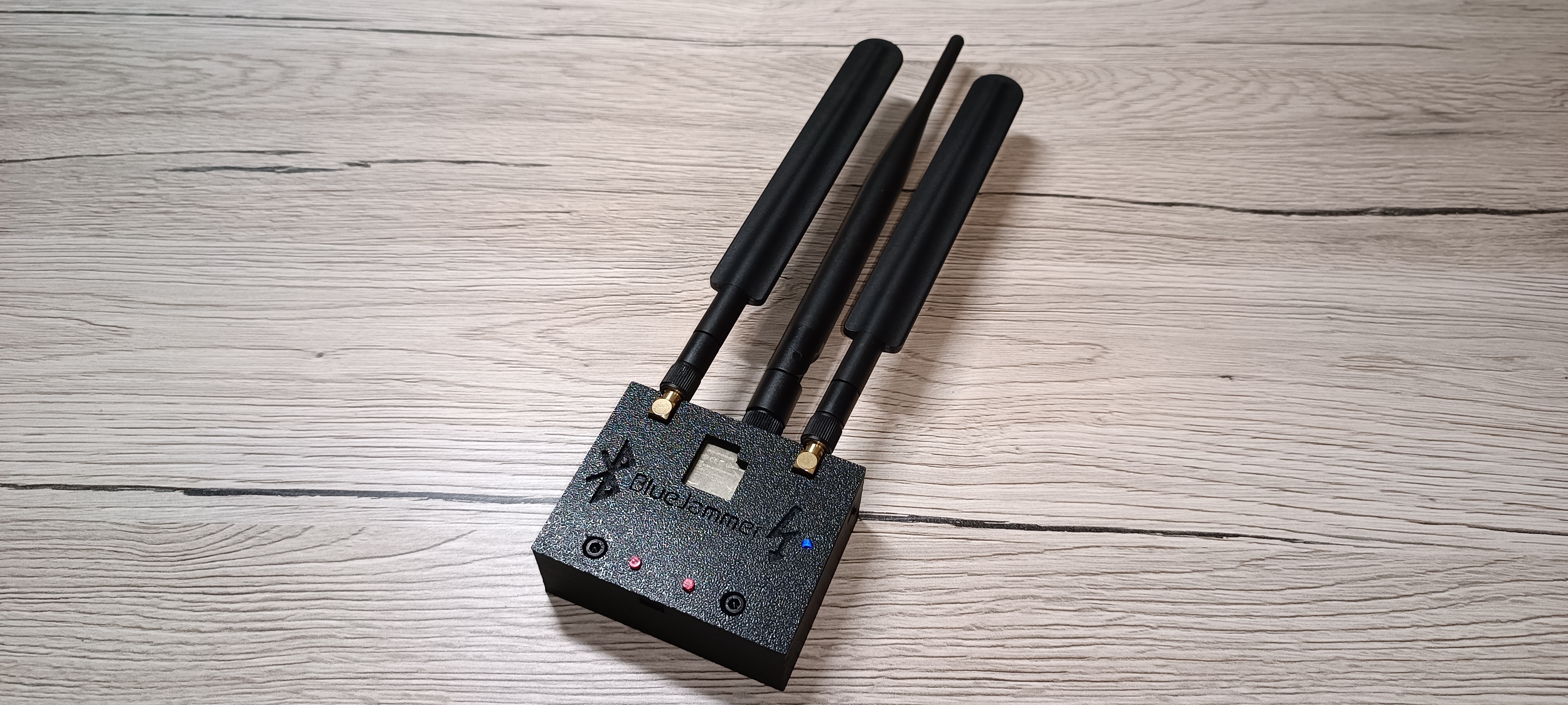
ESP32-BlueJammer
The ESP32-BlueJammer disrupts various devices using an ESP32 NodeMCU and nRF modules, causing plenty of noise and sending unnecessary packets (DoS).
It interrupts:
audio in speakers, smartphone connections, WiFi, RC Drones (etc.), IoT devices, and much more communicating on 2.4GHz!
Ideal for controlled disruption and security testing. Based on 2,4GHz communication.
It has a big range (over 30Meters - may vary on your antenna and hardware setup!) on newest Bluetooth versions with casual 2.4GHz antennas, you can easily increase this aswell by taking some simple "bigger" router antennas. An amplifier (2.4GHz) may be an good option too!
TikTok video with a complete tutorial
operation channels
- Bluetooth = 80CH
- BLE = 40CH
- WiFi = 14CH
- RC drones, etc. = 1-125CH
hardware
- ESP32 Dev Module (such as ESP32-WROOM-32U)
- nRF24L01+PA+LNA (2x)
- 10UF capacitor (2x) any voltage above 5V
If you're looking to add a battery:
- 3.7V Li-Ion battery
- JST PH 2,0 connector
- TP4056 Charging Module
- 3mm LED (blue)
- 470k Ohm resistor
- mini slide switch
To screw the 3D printed case together you must have:
- M3X16 screws (2x)
- M3 Nuts (2x)
THE 3D printed case fits ONLY a PCB size of 7cm x 5.5cm and you'll need to drill out 2 holes according for the M3 screws to fit through the PCB!
flashing ESP32 via webflasher
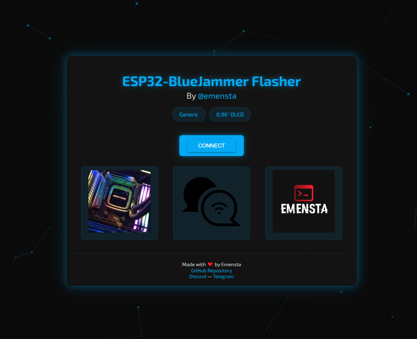
I've created a webflasher to make it super easy for you to flash your ESP32 chip with the ESP32-BlueJammer firmware of your choice!
- Visit ESP32-BlueJammerFlasher
- Connect your ESP32 via a data USB cable
- Choose your firmware, chip and connect
- Flash the firmware of your choice :D
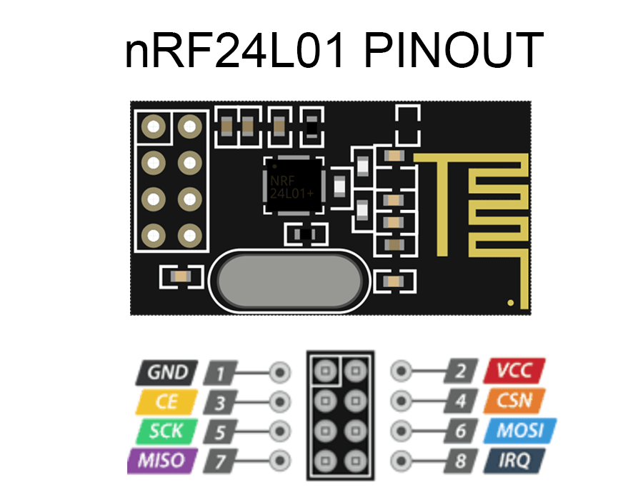
ESP32-nRF24L01+ pinout
Here are both pinouts for HSPI and VSPI. You need both nRF24L01 modules connected in order to achieve full capability of the device.
nRF24L01+ pinout
HSPI
| 1st nRF24L01 module Pin | HSPI Pin (ESP32) | 10uf capacitor |
|---|---|---|
| VCC | 3.3V | (+) capacitor |
| GND | GND | (-) capacitor |
| CE | GPIO 16 | |
| CSN | GPIO 15 | |
| SCK | GPIO 14 | |
| MOSI | GPIO 13 | |
| MISO | GPIO 12 | |
| IRQ |
VSPI
| 2nd nRF24L01 module Pin | VSPI Pin (ESP32) | 10uf capacitor |
|---|---|---|
| VCC | 3.3V | (+) capacitor |
| GND | GND | (-) capacitor |
| CE | GPIO 22 | |
| CSN | GPIO 21 | |
| SCK | GPIO 18 | |
| MOSI | GPIO 23 | |
| MISO | GPIO 19 | |
| IRQ |
Battery mod
| 3.7V Li-Ion battery | JST PH 2.0 connector | TP4056 Charging Module | Mini Slide Switch | ESP32 | 3mm LED (blue) | 470k Ohm Resistor |
|---|---|---|---|---|---|---|
| (+) battery | (+) JST | B+ | ||||
| (-) battery | (-) JST | B- | ||||
| OUT + | switch (+) input | |||||
| OUT - | GND | resistor output | ||||
| switch (+) output | 3V3 | (+) LED | ||||
| (-) LED | resistor input |
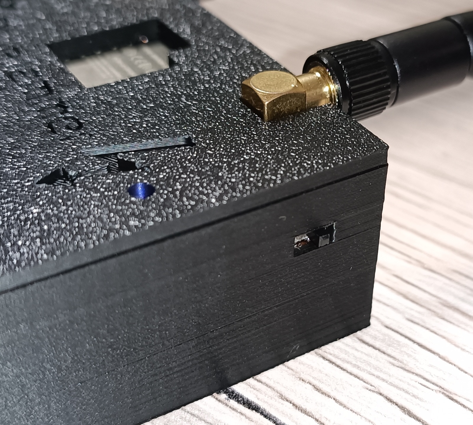
3D printed case
Access to the ESP32 micro-USB port, aswell as to both EN & Boot buttons
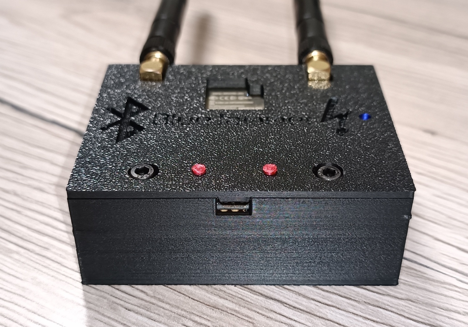
TP4056 charging port access with charging state indicator holes (red=charging - blue=fully charged)
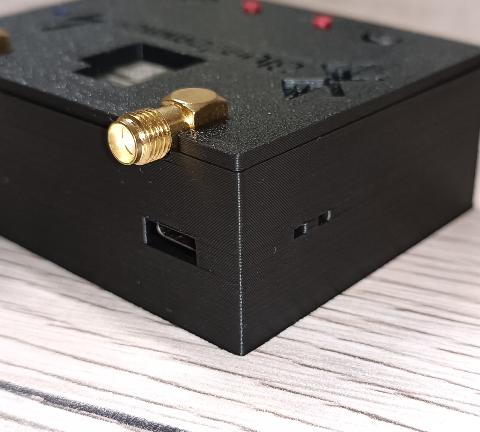
On/off switch with blue indicator LED
3D model view [download .stl]
Here's a look at the model itself

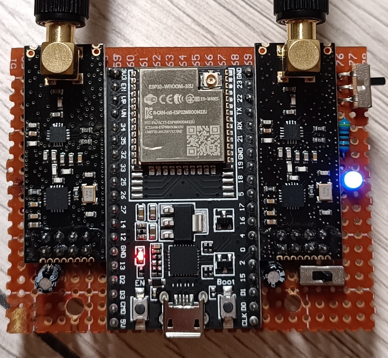
PCB
That's how the components are placed (PCB size=7cm x 5.5cm - Larger sizes will NOT fit in the case!)
Discord
You can join my Discord server here!
Donate
If you enjoy what I do and want to support me in creating more content and sharing new ideas, feel free to support me!
PayPal.me